The plot below shows the sweep frequency response of the rf board in an ic 775 radio.
Rf roofing filter.
The improvement in first if selectivity is dramatic.
It is usually found after the first receiver mixer.
Filter insertion loss plus a few db.
It is usually found after the first receiver mixer.
The rf amplifier has optimized nf points and the over sized wide range rf transformer exhibits minimum saturation in strong signal processing.
The roofing filter mod inserts a narrow band crystal filter between the rf assembly and the if board.
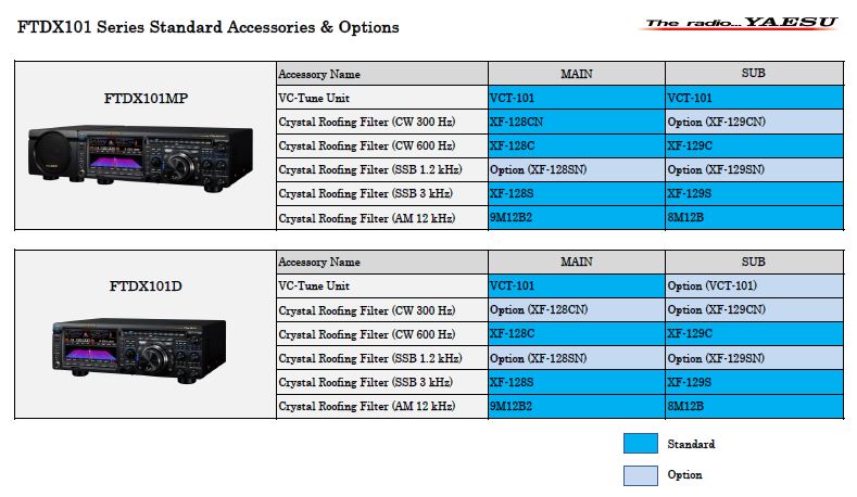
It is also the only other rig besides the ftdx 5000 that has down conversion crystal roofing filters.
The essential elements in receiver performance are the rf amplifier and the 1st mixer.
The narrow band sdr receiver removes strong out of band signals by using a superheterodyne method with narrow band roofing filters which significantly attenuates unwanted out of band frequency components and the wanted signals within the passband are converted to digital by a high resolution 18 bit a d converter and sent to an fpga field programmable gate array for signal processing.
My 1977 dream rig now joining the shack lineup.
A look at filtering and drift on a classic yg 455c 1 for the ts 830s adopting the yg 455c 1 for use in the kenwood ts 830s 2nd if kenwood ts 820s.
Reducing the bandwidth at this point in the radio helps to keep strong off frequency signals out of the second mixer where they can cause intermodulation.
O needs vhf roofing filters wide cheap or narrow expensive o excellent image rejection o close in dr varies down conversion architecture 9 mhz typical 1 st if o performance near if is not uniform o image rejection near ham bands requires design attention o needs only hf roofing filters narrow cheap.
The narrow band sdr receiver removes strong out of band signals by using a superheterodyne method with narrow band roofing filters which significantly attenuates unwanted out of band frequency components and the wanted signals within the passband are converted to digital by a high resolution 18 bit a d converter and sent to an fpga field programmable gate array for signal processing.
Have technology from space aliens nsa yet i still can t filter the guy up the band.
The goal of a roofing filter is to limit the passband of the first intermediate frequency if stage.
A four position dip switch is used to set up the roofing filter function.
A supplied jumper cable connects back to the if board.
Why your filter is not working.
The wider curve is the oem response and the narrow curve is with the inrad roofing filter mod added.
Two coax cables insert the roofing filter between the rf board and the 9 mhz if board.
The n1 n2 switching cable gets extended and plugged into the inrad board.
Transmission is not changed as it does not pass through the roofing filter.

